
Garmin GA 35

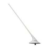
Garmin GA 35 is an active GPS/WAAS antenna with a teardrop footprint and a TNC connector, listed by Garmin for GTN Xi and GPS 175 installations. Choose P/N and condition on this page. Four 8-32 screws and an O-ring are supplied.

View full details →
L1 GPS/WAAS, ±10 MHz
1575 MHz
Signal and DC on one coax
TNC
40 mA nom., 60 mA max.
5 V DC ±10 %
20.6 mm high
0.22 kg
All specifications →
SKU
013-00235-00-SV
Cert
DUAL
Condition
Serviceable (SV)

Choose your version

Pick one option in each step. Price and availability update with your choice.

P/N013-00235-00
Condition

Your selection: P/N: 013-00235-00 · Condition: Serviceable / Overhauled

On request

Price on request

  • Certified parts with full documentation
  • DHL delivery to 50+ countries
  • Expert product support
Have a question about this product? Contact us

Garmin GA 35 GPS/WAAS Antenna

Garmin GA 35 is an active GPS/WAAS antenna for through-skin mounting on top of the aircraft, with a teardrop footprint and a TNC connector. Garmin lists it for GTN Xi and GPS 175 installations. Signal and DC power share one coaxial cable. Select part number and condition above; four 8-32 screws and an O-ring are supplied.

  • Active GPS/WAAS antenna for L1, 1575 MHz ±10 MHz, with right-hand circular polarization and 50 Ω impedance.

  • One TNC connector and one coaxial cable carry the GPS signal to the receiver and DC power to the preamplifier.

  • Supply 5 V DC ±10 % from the receiver, at 40 mA nominal and 60 mA maximum.

  • Garmin lists TSO-C144 for the GA 35. Installation follows the aircraft TC or STC requirements.

  • Teardrop footprint, 20.6 mm high, 0.22 kg.

  • Operating range −55 to +85 °C and up to 55,000 ft; tested to DO-160 lightning direct effects category 1C.

Receiver compatibility

Garmin lists the GA 35 as an approved GPS/WAAS antenna in the GTN Xi Series TSO installation manual (190-02327-02) and in the GPS 175 installation manual (190-02207). The antenna installation instructions leave receiver compatibility to the installation manual of the receiver, so any other receiver needs its own manual checked.

Garmin notes that the GA 35 has the mounting hole pattern of the GA 56, on a physically larger footprint. That matters when an existing antenna is replaced.

Mounting and hardware

Mounting and hardware

The antenna is secured through the skin with four stainless-steel screws, MS24693-C 8-32, tightened evenly to 12–15 in-lb (1.4–1.7 N·m), with an O-ring in the groove on the underside. Garmin supplies the screws and the O-ring. Washers and locking nuts are not supplied and may be part of the doubler plate.

Connector and signal path

Connector and signal path

The TNC connector on the underside joins the antenna to the receiver. The same coaxial cable carries the amplified GPS signal to the receiver and the DC supply from the receiver to the preamplifier, so no separate power wiring is needed. Garmin's data gives a noise figure of 2.5 dB maximum, 50 Ω impedance and 1.5:1 VSWR in dry conditions.

Coax routing distance, loss limits and troubleshooting are in the installation manual of the receiver, and a TNC plug is needed to connect the cable.

Antenna location

The GPS antenna goes on top of the aircraft, as close to level as possible in cruise attitude and, where practical, away from the tail to limit airframe shadowing. Garmin asks for at least 0.6 m (2 ft) to any VHF COM antenna or any antenna transmitting more than 25 W, and 230 mm (9 in) minimum, 300 mm (12 in) where practical, centre to centre from other antennas. Distance to the windscreen is at least 75 mm (3 in).

An EMC check of the installed aircraft shows whether VHF COM or ELT interference degrades GPS. If it does, Garmin names a GPS notch filter in line with the offending source.

Grounding and sealing

Garmin recommends a metallic ground plane or skin reaching at least 190 mm (7.5 in) beyond the antenna perimeter. The baseplate is bonded electrically, with DC resistance of 2.5 milliohms or less; paint under the footprint usually stays. Seal with electrical-grade sealant, never construction-grade RTV or sealant containing acetic acid.

Installation approval

Installation follows the aircraft TC or STC requirements, and Garmin calls a doubler essential for structural integrity. Garmin's doubler comes under US AML STC SA02018SE-D, which is not an EASA approval. For an EU aircraft the route is an approved modification and a Certificate of Release to Service.

Colour versions

Garmin lists the GA 35 in three colours: 013-00235-00 white, -01 black and -02 olive green, matching Aero Antenna part AT575-93G(W/B/O)-TNCF-000-RG-27-NM. The offer covers the white -00.

Recommended accessories

Can't find the right part?

Our parts specialists will find hard-to-get components, check that a part suits your aircraft and arrange exchange units.

  • Hard-to-find and obsolete parts
  • A check that the part fits your aircraft, with the right paperwork
  • Exchange and overhauled units

Send us your question using the form. We will reply by e-mail.